


How to Test Tube Receivers Without Risking Damage

A tube receiver that has been silent for decades can be tempting to plug in and try. That first switch-on, however, is where an original power transformer, rectifier tube, speaker field coil, or irreplaceable dial lamp can be lost. Knowing how to test tube receivers begins with restraint: learn what is present, what is unsafe, and what must be addressed before power is applied.
For a 1930s tabletop radio, a postwar console, or a 1960s tube tuner-receiver, testing is not simply about finding a bad tube. It is a careful process of protecting the electronics while building a clear picture of the set's condition. The receiver may be an estate find, a family heirloom, or a piece of audio history worth preserving in its proper form.
Start With Safety, Not the Power Switch
Tube equipment operates at voltages that can seriously injure or kill. Even after the cord is unplugged, filter capacitors may retain a dangerous charge. A receiver with a transformerless "hot chassis" design presents additional shock risks because parts of its circuitry can be connected directly to the AC line.
Do not test a newly acquired receiver on a kitchen counter, near children or pets, or while standing on a damp floor. Remove rings, watches, and loose jewelry. Use a clean, well-lit bench and keep the chassis supported so it cannot tip or slide. If you do not have experience working around high-voltage electronics, the safest test is an unplugged inspection followed by service from a qualified vintage-radio technician.
Before any internal work, photograph the chassis from several angles. Record the model number, tube lineup, speaker connections, and unusual wiring. These records are valuable when comparing the set against its schematic or when preserving evidence of original construction.
How to Test Tube Receivers Before Applying Power
Begin with the cabinet and cord. A cracked or brittle power cord, damaged plug, missing strain relief, or exposed conductor means the receiver should not be energized. Replace unsafe line cords in a manner that respects the equipment's layout and appearance. On valuable radios, retain the original cord with the set when practical, even if it can no longer be used.
With the receiver unplugged, remove the chassis carefully and inspect it under good light. Look for rodent damage, burned resistors, melted wax, loose hardware, corrosion, and evidence of prior repairs. Not every old component is a fault. Dust, aged lacquer, and darkened tube bases are common. What matters is distinguishing ordinary age from heat damage, leaking capacitors, deteriorated insulation, or wiring that has been altered carelessly.
Pay close attention to paper and electrolytic capacitors. Original wax-paper capacitors commonly become electrically leaky with age. Electrolytic filter capacitors can fail shorted, draw excessive current, and damage a power transformer or rectifier. A receiver that looks untouched may be historically interesting, but originality does not make its aging capacitors safe to operate.
Several cold checks with a multimeter can reveal serious problems before power enters the chassis:
Verify continuity through the power cord, switch, fuse holder, and transformer primary, where applicable.
Check that the speaker voice coil and, on many older radios, the field coil are not open.
Measure continuity of output-transformer and power-transformer windings against the schematic when one is available.
Look for a direct short between the AC line and chassis in sets where the design should isolate them.
Inspect tube sockets for loose contacts, broken locator keys, and signs of arcing or overheating.
These readings do not certify that a receiver is ready to play. They do help identify failures that could turn a first power-up into an expensive one.
Test the Tubes, But Do Not Stop There
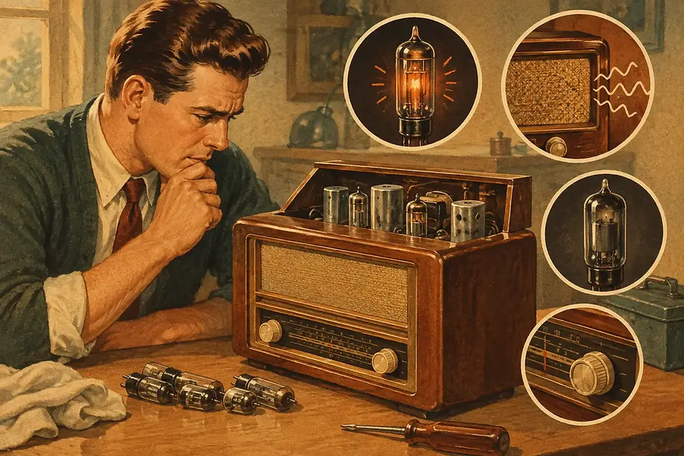
A tube tester is useful for identifying tubes with shorts, very weak emission, or gas-related problems. Test each tube according to its correct type number, and handle older glass envelopes gently. A tube with a white or milky appearance inside has lost its vacuum and should be replaced. A tube with a darkened silver getter, by contrast, is often perfectly normal.
Tube testers have limits. A tube may test good and still perform poorly in a radio because of circuit conditions, intermittent socket contact, incorrect bias, or a failing capacitor. Conversely, a tube that reads somewhat weak may still work acceptably in a low-demand stage. In vintage receivers, replacing every tube simply because it is old is rarely thoughtful restoration.
Clean tube pins only as needed, using a suitable contact cleaner sparingly. Avoid aggressive scraping, which can remove plating or loosen fragile pins. Confirm that each tube is returned to the correct socket before any powered testing. A misplaced rectifier or output tube can cause immediate damage.
Use Controlled Power for a First Startup
Once unsafe capacitors, compromised wiring, and obvious shorts have been addressed, bring the receiver up slowly with the proper bench equipment. A variable autotransformer, often called a Variac, lets a technician increase line voltage gradually. A dim-bulb tester places an incandescent lamp in series with the receiver and offers a visible indication of excessive current draw. An isolation transformer is essential when servicing transformerless AC/DC equipment.
These tools serve different purposes. A Variac does not provide isolation. A dim-bulb tester does not repair a failing receiver. An isolation transformer reduces a particular shock hazard but does not make high-voltage work harmless. Used together with sound judgment, they give the technician time to stop when current draw rises unexpectedly, a transformer hums, smoke appears, or a capacitor begins to heat.
During the first controlled power-up, watch and listen. Tubes should warm gradually; the rectifier should not flash over; and no component should smoke or produce a sharp burning odor. A modest hum may indicate power supply trouble, while silence can point to many possible faults. Shut down immediately if the dim-bulb tester remains unusually bright, the current climbs rapidly, or any transformer becomes hot within minutes.
Never leave an unfamiliar tube receiver powered unattended. A set that begins working is not automatically safe for extended use.
Measure Voltages With a Schematic as Your Map
After the power supply has proven stable, voltage measurements can narrow down remaining faults. The schematic provides expected operating voltages at the rectifier, filter capacitors, output stage, and earlier audio or radio-frequency stages. Readings that are substantially high or low often tell a more useful story than swapping parts at random.
This is the stage that deserves particular care. Clip meter leads with power off whenever possible, then energize the receiver and keep one hand away from the chassis. Use insulated probes rated for the voltage involved. Know whether the chassis is the proper reference point for that circuit, since some designs use a floating or isolated return rather than chassis ground.
Start at the power supply. Confirm that high voltage is present after the rectifier and that ripple is not excessive. Then verify output-tube plate, screen, and cathode conditions against the service data. A low high-voltage supply can cause weak audio throughout the receiver, while an output stage drawing too much current can threaten the output transformer.
If the audio section responds but the radio receives poorly, move methodically through the signal path. Test whether a volume control produces a hum when touched through an appropriate insulated test method, check antenna and oscillator circuits, and examine coils for open windings. Alignment should come only after the receiver is electrically stable. Attempting alignment while capacitors drift or supply voltage is incorrect wastes time and can mask the real issue.
Preserve the Receiver While Restoring Its Voice
A good test process protects both performance and provenance. Keep original parts that are removed, especially labeled capacitors, unusual controls, shields, dial components, and hardware. Document changes under the chassis. Safety-related replacement parts can often be installed neatly without making a receiver look carelessly modernized.
Cabinet condition deserves the same patience. Do not spray cleaner into a dial scale, polish away a desirable patina, or force a frozen control shaft. The warm glow of a restored receiver means more when the cabinet, dial, and original character have been treated with equal respect.
When the job calls for more than a careful owner should attempt, Regal Sound Design approaches each receiver as both a working instrument and a surviving piece of history. The goal is not merely to make a dial light up, but to give the set a dependable chance to fill a room with the sound and presence that made it worth keeping.


Comments